While it doesn’t take a lot of know-how to operate a fully automatic camera, serious photography—whether at the hobbyist or professional level—has always required a tremendous amount of craftsmanship and technical understanding. In “wet darkroom” work, everything from paper type to chemical mixtures to the amount of agitation applied to a particular chemical has a bearing on the quality of your final print. As such, skilled film photographers have to have an in- depth understanding of the nature of their papers, chemicals, and equipment.
Digital photography is no different. To fully exploit your camera’s capabilities— and to be able to effectively edit and improve your images—you must understand some of the fundamental principles and technologies behind digital imaging.
As mentioned in Chapter 1, “Introduction,” the only real difference between a digital camera and a film camera is that a digital camera does not use film to record an image. However, this one fundamental difference affects all of the other systems on the camera, from the lens to the light meter. Consequently, knowing some of the technical details of how a digital camera works will help you select the right camera and help you better understand how to make certain decisions when shooting.
SOMETHING OLD, SOMETHING NEW
Just like a film camera, your digital camera records an image by using a lens to focus light through an aperture and a shutter and then onto a focal plane. By opening or closing the aperture and by changing the amount of time the shutter is open, the photographer can control how the focal plane is exposed. As we’ll see later, exposure control allows the photographer to change the degree to which the camera “freezes” motion, how well the film records contrast and color saturation, and which parts of the image are in focus.
While a film camera has a piece of film sitting on the focal plane, in a digital camera, an image sensor is mounted on the focal plane. An image sensor is a special type of silicon chip that is light sensitive. Currently, there are two major types of image sensors available: the charge-coupled device (CCD), and the Complementary Metal Oxide Semiconductor (CMOS). CCDs are more popular than CMOS chips, but the role of both is the same. When you take a picture, the light falling on the image sensor is sampled, converted into electrical signals. After the image sensor is exposed, these signals are boosted by an amplifier and sent to an analog-to-digital converter that turns the signals into digits. These digits are then sent to an onboard computer for processing. Once the computer has calculated the final image, the new image data is stored on a memory card. (See Figure 2.1.)

FIGURE 2.1 Light passes into a digital camera, just as it would in a film camera. However, instead of hitting a piece of film, it is digitized by a computer chip and passed to an onboard computer to create an image.
Although the mechanics are simple to explain, to really understand how a digi- tal camera functions, you must know a little color theory.
A LITTLE COLOR THEORY
In 1869, James Clerk Maxwell asked photographer Thomas Sutton (the inventor of the SLR camera) to take three black-and-white photographs of a tartan ribbon. Maxwell wanted to test a theory he had about a possible method for creating color photographs. He asked Sutton to place a different filter over the camera for each shot: first, a red filter, then green, and then blue. After the film was developed, Maxwell projected all three black-and-white pictures onto a screen using three pro- jectors fitted with the same filters that were used to shoot the photos. When the im- ages were projected directly on top of each other, the images combined and Maxell had the world’s first color photo.
This process was hardly convenient. Unfortunately, it took another 30 years to turn Maxwell’s discovery into a commercially viable product. This happened in 1903, when the Lumière brothers used red, green, and blue dyes to color grains of starch that could be applied to glass plates to create color images. They called their process Autochrome, and it was the first successful color printing process.
In grammar school, you probably learned that you could mix primary colors to- gether to create other colors. Painters have used this technique for centuries, of course, but what Maxwell demonstrated is that, although you can mix paints to- gether to create darker colors, light mixes together to create lighter colors. Or, to use some jargon, paint mixes in a subtractive process (as you mix, you subtract color to create black), whereas light mixes in an additive process (as you mix, you add color to create white). Note that Maxwell did not discover light’s additive properties— Newton had done similar experiments long before—but Maxwell was the first to apply the properties to photography.

FIGURE 2.2 Red, green, and blue—the three additive primary colors of light—can be mixed together to create other colors. As you combine them, the resulting color gets lighter, eventually becoming white. Note also that where the colors overlap they create the secondary primary colors—cyan, magenta, and yellow. These are the primary colors of ink.
Your digital camera makes color images using pretty much the same process Maxwell used in 1860: it combines three different black-and-white images to create a full-color final image.
The image shown in Figure 2.3 is called an RGB image because it uses red, green, and blue channels to create a color image.
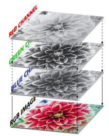
FIGURE 2.3 In a digital image, three separate red, green, and blue channels are combined to create a final, full-color picture.
This color theory is not just a trivial history lesson. Understanding that your full color images are composed of separate channels will come in very handy later, when you start editing. Very often, you’ll correct color casts and adjust your images by viewing and manipulating individual color channels.
You Say “Black and White,” I Say “Grayscale”
Although film photographers use the term black-and-white to denote an image that lacks color, in the digital world it’s better to use the term grayscale. As we saw in Figure 1.1, your computer can create an image that is composed of only black and white pixels. Consequently, it’s sometimes important to distinguish between an image that is made up of black and white pixels, and one that is made up of pixels of varying shades of gray.
In the century and a half since Maxwell’s discovery, many other ways of repre- senting color have been discovered. For example, another model called L*A*B color (also known as Lab color) uses one channel for lightness information, another channel for greenness or redness, and a third channel for blueness or yellowness. In addition, there is the cyan, magenta, yellow, and black (CMYK) model that printers use.
Each of these approaches is called a color model, and each model has a particular gamut, or range, of colors it can display. Some gamuts are more appropriate to cer- tain tasks than others are, and all are smaller than the range of colors your eye can perceive.
We’ll deal more with gamuts and color models in later chapters. For now, it’s important to understand that digital photos are made up of separate red, green, and blue channels that combine to create a color image.
HOW AN IMAGE SENSOR WORKS
George Smith and Willard Boyle were two engineers employed by Bell Labs. The story goes that one day in late October, the two men spent about an hour sketching out an idea for a new type of semiconductor that could be used for computer mem- ory and for the creation of a solid-state, tubeless video camera. The year was 1969, and in that hour, the two men invented the CCD.
Roughly a year later, Bell Labs created a solid-state video camera using Smith and Boyle’s new chip. Although their original intention was to build a simple cam- era that could be used in a video-telephone device, they soon built a camera that was good enough for broadcast television.
Since then, CCDs have been used in everything from cameras to fax machines. Because video cameras don’t require a lot of resolution (only half a million pixels or so), the CCD worked great for creating video-quality images. For printing pictures, though, you need much higher resolution—millions and millions of pixels. Conse- quently, it wasn’t until recently that CCDs could be manufactured with enough res- olution to compete with photographic film.
CCD VS. CMOS
Ninety to 95 percent of the digital cameras you’ll look at will use CCD image sensors. The rest will use a CMOS chip of some kind. What’s the difference? Because much more re- search has been put into CCD technology, it’s more prevalent. CMOS chips, though, are ac- tually much cheaper to produce than the difficult-to-make CCDs found in most cameras. CMOS chips also consume much less power than does a typical CCD, making for longer camera battery life and fewer overheating problems. CMOS also offers the promise of in- tegrating more functions onto one chip, thereby enabling manufacturers to reduce the number of chips in their cameras. For example, image capture and processing could both be performed on one CMOS chip, further reducing the price of a camera.
Although CMOS used to have a reputation for producing rough images with inferior color, Canon®’s excellent EOS series of digital SLRs have shown that CMOS can be a viable alternative to CCDs.
Both chips register light in the same way, and for the sake of this discussion, the two technologies are interchangeable. In the end, image sensor choice is irrelevant as long as the camera delivers an image quality you like.
Counting Electrons
Photographic film is covered with an emulsion of light-sensitive, silver-laden crys- tals. When light hits the film, the silver atoms clump together. The more light there is, the bigger the clumps. In this way, a piece of film records the varying amounts of light that strike each part of its surface. A piece of color film is actually a stack of three separate layers—one sensitive to red, one to green, and one to blue.
To a degree, you have Albert Einstein to thank for your digital camera, because he was the first to explore the photoelectric effect. It is because of the photoelectric ef- fect that some metals release electrons when exposed to light. (Einstein actually won the 1921 Nobel Prize in physics for his work on the photoelectric effect, not for his work on relativity or gravity, as one might expect.)
The image sensor in your digital camera is a silicon chip that is covered with a grid of small electrodes called photosites, one for each pixel. (See Figure 2.4.)
Before you can shoot a picture, your camera charges the surface of the CCD with electrons. Thanks to the photoelectric effect, when light strikes a particular photosite, the metal in that site releases some of its electrons. Because each photo- site is bounded by nonconducting metal, the electrons remain trapped. In this way, each photosite is like a very shallow well, storing up more and more electrons as more and more photons hit. After exposing the CCD to light, your camera simply has to measure the voltage at each site to determine how many electrons are there and, thus, how much light hits that particular site. (As was discussed in Chapter 1, this process is called sampling.) This measurement is then converted into a number by an analog-to-digital converter.
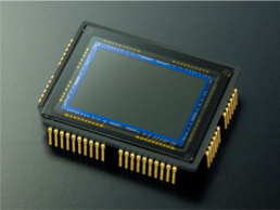
FIGURE 2.4 The sensor from a Nikon D70 has an imaging area of 23.7 mm by 15.6 mm.
Most cameras use either a 12-bit or 14-bit analog-to-digital converter. That is, the electrical charge from each photosite is converted into a 12- or 14-bit number. In the case of a 12-bit converter, this produces a number between 0 and 4,096; with a 14-bit converter, you get a number between 0 and 16,384. Note that an analog-to- digital converter with a higher bit depth doesn’t give your CCD a bigger dynamic range. The brightest and darkest colors it can represent remain the same, but the extra bit depth does mean that the camera will produce finer gradations within that dynamic range. As you’ll see later, how many bits get used in your final image de- pends on the format in which you save the image.
The term charge-coupled device (CCD) is derived from the way the camera reads the charges of the individual photosites. After exposing the CCD, the charges on the first row of photosites are transferred to a read-out register where they are amplified and then sent to an analog-to-digital converter. Each row of charges is electrically coupled to the next row so that, after one row has been read and deleted, all of the other rows move down to fill the now empty space. (See Figure 2.5.)
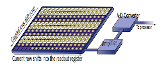
FIGURE 2.5 Rows of photosites on a CCD are coupled together. As the bottom row of photosites is read off the bottom of the CCD, all of the rows above it shift down. This is the coupled in charge-coupled device.
After all the rows of photosites have been read, the CCD is recharged with elec- trons and is ready to shoot another image.
Photosites are sensitive only to how much light they receive; they know nothing about color. As you’ve probably already guessed, to see color your camera needs to perform some type of RGB filtering similar to what James Maxwell did. There are a number of ways to perform this filtering, but the most common is through a single array system, sometimes referred to as a striped array.
Arrays
Consider the images in Figure 2.6. If asked to fill in any “missing” pixels in Figure 2.6a, you’d probably say, “What
are you talking about?” If asked to fill in any “missing” pixels in Figure 2.6b, though, you probably would have no trouble creating the image in Figure 2.7.
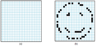
FIGURE 2.6 Although you have no idea what pixels belong in Figure 2.6a, you can probably hazard a guess as to what the missing pixels are in Figure 2.6b.
You would know which pixels you needed to fill in based on the other pixels that were already in the image. In other words, you would have interpolated the new pixels based on the existing information. You might have encountered interpolation if you’ve ever resized a photograph using an image-editing program such as Photo- shop. To resize an image from 2,048 × 1,536 pixels to 4,096 × 3,072 pixels, your image editor has to perform many calculations to determine what color all of those new pixels should be. (Obviously, in this example, your ability to interpolate is based on your ability to recognize a familiar icon—the happy face. An image editor knows nothing about the content of an image, of course, and must interpolate by carefully examining each of the pixels in an image to determine what the colors of any new additional pixels should be.)

FIGURE 2.7 If asked to fill in the “missing” pixels in Figure 2.6b, you would probably come up with an image something like this.
A typical digital camera uses a form of interpolation to create a color image. As we saw in the previous section, the image sensor in your camera is able to create a grayscale image of your subject by measuring the amount of light that strikes each part of the image sensor. To shoot color, your camera performs a variation of the same type of RGB filtering Maxwell used in 1869. Each photosite on your camera’s image sensor is covered by a filter—red, green, or blue. This combination of filters is called a color filter array, and most image sensors use a filter pattern like the one shown in Figure 2.8, called the Bayer Pattern.
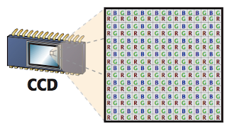
FIGURE 2.8 To see color, alternating pixels on an image sensor are covered with a different colored filter. The color filter array shown here is called the Bayer Pattern.
With these filters, the image sensor can produce separate, incomplete red, green, and blue images. The images are incomplete because the red image, for ex- ample, is missing all of the pixels that were covered with a blue filter, whereas the blue filter is missing all of the pixels that were covered with a red filter. Both the red and blue images are missing the vast number of green-filtered pixels.
A sophisticated interpolation method is used to create a complete color image. Just as you used the partial pixel information in Figure 2.6b to calculate the missing pixels, your digital camera can calculate the color of any given pixel by analyzing all of the ad- jacent pixels. For example, if you look at a particular pixel and see that the pixel to the immediate left of it is a bright red pixel, the pixel to the right is a bright blue pixel, and the pixels above and below are bright green, then the pixel in question is probably white. Why? As Maxwell showed, if you mix red, green, and blue light together, you get white light. (By the way, if you’re wondering why there are so many more green pixels than red or blue pixels, it’s because the eye is most sensitive to green. Conse- quently, it’s better to have as much green information as possible.)
This process of interpolating is called demosaicing, and different vendors employ different approaches to the demosaicing process. For example, many cameras look at only immediately adjacent pixels, but Hewlett-Packard cameras analyze a region up to 9 × 9 pixels. The Fuji® SuperCCD eschews the grid pattern of square photosites in favor of octagonal photosites arranged in a honeycomb pattern. Such a scheme requires even more demosaicing to produce rectangular image pixels, but Fuji claims this process yields a higher resolution. Differences in demosaicing algorithms are one factor that makes some cameras yield better color than others.
Some cameras use a different type of color filter array. Canon, for example, often uses cyan, yellow, green, and magenta filters on the photosites of their image sensors. Because it takes fewer layers of dye to create cyan, yellow, green, and magenta filters than it does to create red, green, and blue filters, more light gets through the CYGM filter to the sensor. (Cyan, yellow, and magenta are the primary colors of ink, and therefore don’t need to be mixed to create the color filters; hence, they aren’t as thick.) More light means a better signal-to-noise ratio, which produces images with less noise.
As another example, Sony sometimes uses red, green, blue, and emerald filters. They claim these filters give a wider color gamut, yielding images with more accu- rate color. Dissenters argue that this approach results in bright areas of the image having a cyan color cast.
Image sensors are often very small, sometimes as small as 1/4 or 1/2 inch (6 or 12 mm, respectively). By comparison, a single frame of 35 mm film is 36 × 23.3 mm. (See Figure 2.9.) The fact that image sensors can be so small is the main reason why digital cameras can be so tiny.
By packing more and more photosites onto an image sensor, chipmakers can in- crease the sensor’s resolution. However, there is a price to pay for this. To pack more photosites onto the surface of the chip, the individual sites have to be made much smaller. As each site gets smaller, its capability to collect light is compromised be- cause it simply doesn’t have as much physical space to catch passing photons. This limitation results in a chip with a poor signal-to-noise ratio; that is, the amount of
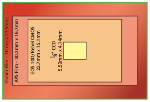
FIGURE 2.9 Most CCDs are very small, particularly when compared to the size of 35 mm film.
good data the chip is collecting—the signal—is muddied by the amount of noise— noise from the camera’s electronics, noise from other nearby electrical sources, noise from cosmic rays raining down from space—the chip is collecting.
In your final image, this signal-to-noise confusion can manifest as grainy pat- terns in your image—visible noise like what you see on a staticky TV channel—or other annoying artifacts. (See the noise example in Figure 4.2.)
To improve the light-collecting capability of tiny photosites, some chipmakers po- sition tiny microlenses over each photosite. These lenses focus the light more tightly into the photosite in an effort to improve the signal-to-noise ratio. However, these lenses can cause problems of their own in the form of artifacts in your final image.
Image sensors suffer from another problem that film lacks. If too much light hits a particular photosite, it can spill over into adjacent photosites. If the camera’s soft- ware isn’t smart enough to recognize that this has happened, you will see a blooming artifact—smearing colors or flared highlights—in your final image. Blooming is more prevalent in a physically smaller image sensor with higher resolution because the photosites are packed more tightly together. This problem is not insurmount- able, and even if your image does suffer from blooming problems from time to time, these artifacts won’t necessarily be visible in your final prints.
As you might expect, interpolating the color in a camera with millions of pixels on its image sensor requires a lot of processing power. Such power (and the memory needed to support it) is one reason why digital cameras have stayed so pricey—lots of fancy chips are necessary to make a digital camera.
Extra Pixels
Not all of the photosites in an image sensor are used for recording your image. Some are used to assess the black levels in your image; others are used for determining white balance. Finally, some pixels are masked away altogether. For example, if the sensor has a square array of pixels but your camera manufacturer wants to create a camera that shoots rectangular images, they will mask out some of the pixels on the edge of the sensor to get the picture shape they want.
»» read more
Digital photography is no different. To fully exploit your camera’s capabilities— and to be able to effectively edit and improve your images—you must understand some of the fundamental principles and technologies behind digital imaging.
As mentioned in Chapter 1, “Introduction,” the only real difference between a digital camera and a film camera is that a digital camera does not use film to record an image. However, this one fundamental difference affects all of the other systems on the camera, from the lens to the light meter. Consequently, knowing some of the technical details of how a digital camera works will help you select the right camera and help you better understand how to make certain decisions when shooting.
SOMETHING OLD, SOMETHING NEW
Just like a film camera, your digital camera records an image by using a lens to focus light through an aperture and a shutter and then onto a focal plane. By opening or closing the aperture and by changing the amount of time the shutter is open, the photographer can control how the focal plane is exposed. As we’ll see later, exposure control allows the photographer to change the degree to which the camera “freezes” motion, how well the film records contrast and color saturation, and which parts of the image are in focus.
While a film camera has a piece of film sitting on the focal plane, in a digital camera, an image sensor is mounted on the focal plane. An image sensor is a special type of silicon chip that is light sensitive. Currently, there are two major types of image sensors available: the charge-coupled device (CCD), and the Complementary Metal Oxide Semiconductor (CMOS). CCDs are more popular than CMOS chips, but the role of both is the same. When you take a picture, the light falling on the image sensor is sampled, converted into electrical signals. After the image sensor is exposed, these signals are boosted by an amplifier and sent to an analog-to-digital converter that turns the signals into digits. These digits are then sent to an onboard computer for processing. Once the computer has calculated the final image, the new image data is stored on a memory card. (See Figure 2.1.)

FIGURE 2.1 Light passes into a digital camera, just as it would in a film camera. However, instead of hitting a piece of film, it is digitized by a computer chip and passed to an onboard computer to create an image.
Although the mechanics are simple to explain, to really understand how a digi- tal camera functions, you must know a little color theory.
A LITTLE COLOR THEORY
In 1869, James Clerk Maxwell asked photographer Thomas Sutton (the inventor of the SLR camera) to take three black-and-white photographs of a tartan ribbon. Maxwell wanted to test a theory he had about a possible method for creating color photographs. He asked Sutton to place a different filter over the camera for each shot: first, a red filter, then green, and then blue. After the film was developed, Maxwell projected all three black-and-white pictures onto a screen using three pro- jectors fitted with the same filters that were used to shoot the photos. When the im- ages were projected directly on top of each other, the images combined and Maxell had the world’s first color photo.
This process was hardly convenient. Unfortunately, it took another 30 years to turn Maxwell’s discovery into a commercially viable product. This happened in 1903, when the Lumière brothers used red, green, and blue dyes to color grains of starch that could be applied to glass plates to create color images. They called their process Autochrome, and it was the first successful color printing process.
In grammar school, you probably learned that you could mix primary colors to- gether to create other colors. Painters have used this technique for centuries, of course, but what Maxwell demonstrated is that, although you can mix paints to- gether to create darker colors, light mixes together to create lighter colors. Or, to use some jargon, paint mixes in a subtractive process (as you mix, you subtract color to create black), whereas light mixes in an additive process (as you mix, you add color to create white). Note that Maxwell did not discover light’s additive properties— Newton had done similar experiments long before—but Maxwell was the first to apply the properties to photography.

FIGURE 2.2 Red, green, and blue—the three additive primary colors of light—can be mixed together to create other colors. As you combine them, the resulting color gets lighter, eventually becoming white. Note also that where the colors overlap they create the secondary primary colors—cyan, magenta, and yellow. These are the primary colors of ink.
Your digital camera makes color images using pretty much the same process Maxwell used in 1860: it combines three different black-and-white images to create a full-color final image.
The image shown in Figure 2.3 is called an RGB image because it uses red, green, and blue channels to create a color image.

FIGURE 2.3 In a digital image, three separate red, green, and blue channels are combined to create a final, full-color picture.
This color theory is not just a trivial history lesson. Understanding that your full color images are composed of separate channels will come in very handy later, when you start editing. Very often, you’ll correct color casts and adjust your images by viewing and manipulating individual color channels.
You Say “Black and White,” I Say “Grayscale”
Although film photographers use the term black-and-white to denote an image that lacks color, in the digital world it’s better to use the term grayscale. As we saw in Figure 1.1, your computer can create an image that is composed of only black and white pixels. Consequently, it’s sometimes important to distinguish between an image that is made up of black and white pixels, and one that is made up of pixels of varying shades of gray.
In the century and a half since Maxwell’s discovery, many other ways of repre- senting color have been discovered. For example, another model called L*A*B color (also known as Lab color) uses one channel for lightness information, another channel for greenness or redness, and a third channel for blueness or yellowness. In addition, there is the cyan, magenta, yellow, and black (CMYK) model that printers use.
Each of these approaches is called a color model, and each model has a particular gamut, or range, of colors it can display. Some gamuts are more appropriate to cer- tain tasks than others are, and all are smaller than the range of colors your eye can perceive.
We’ll deal more with gamuts and color models in later chapters. For now, it’s important to understand that digital photos are made up of separate red, green, and blue channels that combine to create a color image.
HOW AN IMAGE SENSOR WORKS
George Smith and Willard Boyle were two engineers employed by Bell Labs. The story goes that one day in late October, the two men spent about an hour sketching out an idea for a new type of semiconductor that could be used for computer mem- ory and for the creation of a solid-state, tubeless video camera. The year was 1969, and in that hour, the two men invented the CCD.
Roughly a year later, Bell Labs created a solid-state video camera using Smith and Boyle’s new chip. Although their original intention was to build a simple cam- era that could be used in a video-telephone device, they soon built a camera that was good enough for broadcast television.
Since then, CCDs have been used in everything from cameras to fax machines. Because video cameras don’t require a lot of resolution (only half a million pixels or so), the CCD worked great for creating video-quality images. For printing pictures, though, you need much higher resolution—millions and millions of pixels. Conse- quently, it wasn’t until recently that CCDs could be manufactured with enough res- olution to compete with photographic film.
CCD VS. CMOS
Ninety to 95 percent of the digital cameras you’ll look at will use CCD image sensors. The rest will use a CMOS chip of some kind. What’s the difference? Because much more re- search has been put into CCD technology, it’s more prevalent. CMOS chips, though, are ac- tually much cheaper to produce than the difficult-to-make CCDs found in most cameras. CMOS chips also consume much less power than does a typical CCD, making for longer camera battery life and fewer overheating problems. CMOS also offers the promise of in- tegrating more functions onto one chip, thereby enabling manufacturers to reduce the number of chips in their cameras. For example, image capture and processing could both be performed on one CMOS chip, further reducing the price of a camera.
Although CMOS used to have a reputation for producing rough images with inferior color, Canon®’s excellent EOS series of digital SLRs have shown that CMOS can be a viable alternative to CCDs.
Both chips register light in the same way, and for the sake of this discussion, the two technologies are interchangeable. In the end, image sensor choice is irrelevant as long as the camera delivers an image quality you like.
Counting Electrons
Photographic film is covered with an emulsion of light-sensitive, silver-laden crys- tals. When light hits the film, the silver atoms clump together. The more light there is, the bigger the clumps. In this way, a piece of film records the varying amounts of light that strike each part of its surface. A piece of color film is actually a stack of three separate layers—one sensitive to red, one to green, and one to blue.
To a degree, you have Albert Einstein to thank for your digital camera, because he was the first to explore the photoelectric effect. It is because of the photoelectric ef- fect that some metals release electrons when exposed to light. (Einstein actually won the 1921 Nobel Prize in physics for his work on the photoelectric effect, not for his work on relativity or gravity, as one might expect.)
The image sensor in your digital camera is a silicon chip that is covered with a grid of small electrodes called photosites, one for each pixel. (See Figure 2.4.)
Before you can shoot a picture, your camera charges the surface of the CCD with electrons. Thanks to the photoelectric effect, when light strikes a particular photosite, the metal in that site releases some of its electrons. Because each photo- site is bounded by nonconducting metal, the electrons remain trapped. In this way, each photosite is like a very shallow well, storing up more and more electrons as more and more photons hit. After exposing the CCD to light, your camera simply has to measure the voltage at each site to determine how many electrons are there and, thus, how much light hits that particular site. (As was discussed in Chapter 1, this process is called sampling.) This measurement is then converted into a number by an analog-to-digital converter.

FIGURE 2.4 The sensor from a Nikon D70 has an imaging area of 23.7 mm by 15.6 mm.
Most cameras use either a 12-bit or 14-bit analog-to-digital converter. That is, the electrical charge from each photosite is converted into a 12- or 14-bit number. In the case of a 12-bit converter, this produces a number between 0 and 4,096; with a 14-bit converter, you get a number between 0 and 16,384. Note that an analog-to- digital converter with a higher bit depth doesn’t give your CCD a bigger dynamic range. The brightest and darkest colors it can represent remain the same, but the extra bit depth does mean that the camera will produce finer gradations within that dynamic range. As you’ll see later, how many bits get used in your final image de- pends on the format in which you save the image.
The term charge-coupled device (CCD) is derived from the way the camera reads the charges of the individual photosites. After exposing the CCD, the charges on the first row of photosites are transferred to a read-out register where they are amplified and then sent to an analog-to-digital converter. Each row of charges is electrically coupled to the next row so that, after one row has been read and deleted, all of the other rows move down to fill the now empty space. (See Figure 2.5.)

FIGURE 2.5 Rows of photosites on a CCD are coupled together. As the bottom row of photosites is read off the bottom of the CCD, all of the rows above it shift down. This is the coupled in charge-coupled device.
After all the rows of photosites have been read, the CCD is recharged with elec- trons and is ready to shoot another image.
Photosites are sensitive only to how much light they receive; they know nothing about color. As you’ve probably already guessed, to see color your camera needs to perform some type of RGB filtering similar to what James Maxwell did. There are a number of ways to perform this filtering, but the most common is through a single array system, sometimes referred to as a striped array.
Arrays
Consider the images in Figure 2.6. If asked to fill in any “missing” pixels in Figure 2.6a, you’d probably say, “What
are you talking about?” If asked to fill in any “missing” pixels in Figure 2.6b, though, you probably would have no trouble creating the image in Figure 2.7.

FIGURE 2.6 Although you have no idea what pixels belong in Figure 2.6a, you can probably hazard a guess as to what the missing pixels are in Figure 2.6b.
You would know which pixels you needed to fill in based on the other pixels that were already in the image. In other words, you would have interpolated the new pixels based on the existing information. You might have encountered interpolation if you’ve ever resized a photograph using an image-editing program such as Photo- shop. To resize an image from 2,048 × 1,536 pixels to 4,096 × 3,072 pixels, your image editor has to perform many calculations to determine what color all of those new pixels should be. (Obviously, in this example, your ability to interpolate is based on your ability to recognize a familiar icon—the happy face. An image editor knows nothing about the content of an image, of course, and must interpolate by carefully examining each of the pixels in an image to determine what the colors of any new additional pixels should be.)

FIGURE 2.7 If asked to fill in the “missing” pixels in Figure 2.6b, you would probably come up with an image something like this.
A typical digital camera uses a form of interpolation to create a color image. As we saw in the previous section, the image sensor in your camera is able to create a grayscale image of your subject by measuring the amount of light that strikes each part of the image sensor. To shoot color, your camera performs a variation of the same type of RGB filtering Maxwell used in 1869. Each photosite on your camera’s image sensor is covered by a filter—red, green, or blue. This combination of filters is called a color filter array, and most image sensors use a filter pattern like the one shown in Figure 2.8, called the Bayer Pattern.

FIGURE 2.8 To see color, alternating pixels on an image sensor are covered with a different colored filter. The color filter array shown here is called the Bayer Pattern.
With these filters, the image sensor can produce separate, incomplete red, green, and blue images. The images are incomplete because the red image, for ex- ample, is missing all of the pixels that were covered with a blue filter, whereas the blue filter is missing all of the pixels that were covered with a red filter. Both the red and blue images are missing the vast number of green-filtered pixels.
A sophisticated interpolation method is used to create a complete color image. Just as you used the partial pixel information in Figure 2.6b to calculate the missing pixels, your digital camera can calculate the color of any given pixel by analyzing all of the ad- jacent pixels. For example, if you look at a particular pixel and see that the pixel to the immediate left of it is a bright red pixel, the pixel to the right is a bright blue pixel, and the pixels above and below are bright green, then the pixel in question is probably white. Why? As Maxwell showed, if you mix red, green, and blue light together, you get white light. (By the way, if you’re wondering why there are so many more green pixels than red or blue pixels, it’s because the eye is most sensitive to green. Conse- quently, it’s better to have as much green information as possible.)
This process of interpolating is called demosaicing, and different vendors employ different approaches to the demosaicing process. For example, many cameras look at only immediately adjacent pixels, but Hewlett-Packard cameras analyze a region up to 9 × 9 pixels. The Fuji® SuperCCD eschews the grid pattern of square photosites in favor of octagonal photosites arranged in a honeycomb pattern. Such a scheme requires even more demosaicing to produce rectangular image pixels, but Fuji claims this process yields a higher resolution. Differences in demosaicing algorithms are one factor that makes some cameras yield better color than others.
Some cameras use a different type of color filter array. Canon, for example, often uses cyan, yellow, green, and magenta filters on the photosites of their image sensors. Because it takes fewer layers of dye to create cyan, yellow, green, and magenta filters than it does to create red, green, and blue filters, more light gets through the CYGM filter to the sensor. (Cyan, yellow, and magenta are the primary colors of ink, and therefore don’t need to be mixed to create the color filters; hence, they aren’t as thick.) More light means a better signal-to-noise ratio, which produces images with less noise.
As another example, Sony sometimes uses red, green, blue, and emerald filters. They claim these filters give a wider color gamut, yielding images with more accu- rate color. Dissenters argue that this approach results in bright areas of the image having a cyan color cast.
Image sensors are often very small, sometimes as small as 1/4 or 1/2 inch (6 or 12 mm, respectively). By comparison, a single frame of 35 mm film is 36 × 23.3 mm. (See Figure 2.9.) The fact that image sensors can be so small is the main reason why digital cameras can be so tiny.
By packing more and more photosites onto an image sensor, chipmakers can in- crease the sensor’s resolution. However, there is a price to pay for this. To pack more photosites onto the surface of the chip, the individual sites have to be made much smaller. As each site gets smaller, its capability to collect light is compromised be- cause it simply doesn’t have as much physical space to catch passing photons. This limitation results in a chip with a poor signal-to-noise ratio; that is, the amount of

FIGURE 2.9 Most CCDs are very small, particularly when compared to the size of 35 mm film.
good data the chip is collecting—the signal—is muddied by the amount of noise— noise from the camera’s electronics, noise from other nearby electrical sources, noise from cosmic rays raining down from space—the chip is collecting.
In your final image, this signal-to-noise confusion can manifest as grainy pat- terns in your image—visible noise like what you see on a staticky TV channel—or other annoying artifacts. (See the noise example in Figure 4.2.)
To improve the light-collecting capability of tiny photosites, some chipmakers po- sition tiny microlenses over each photosite. These lenses focus the light more tightly into the photosite in an effort to improve the signal-to-noise ratio. However, these lenses can cause problems of their own in the form of artifacts in your final image.
Image sensors suffer from another problem that film lacks. If too much light hits a particular photosite, it can spill over into adjacent photosites. If the camera’s soft- ware isn’t smart enough to recognize that this has happened, you will see a blooming artifact—smearing colors or flared highlights—in your final image. Blooming is more prevalent in a physically smaller image sensor with higher resolution because the photosites are packed more tightly together. This problem is not insurmount- able, and even if your image does suffer from blooming problems from time to time, these artifacts won’t necessarily be visible in your final prints.
As you might expect, interpolating the color in a camera with millions of pixels on its image sensor requires a lot of processing power. Such power (and the memory needed to support it) is one reason why digital cameras have stayed so pricey—lots of fancy chips are necessary to make a digital camera.
Extra Pixels
Not all of the photosites in an image sensor are used for recording your image. Some are used to assess the black levels in your image; others are used for determining white balance. Finally, some pixels are masked away altogether. For example, if the sensor has a square array of pixels but your camera manufacturer wants to create a camera that shoots rectangular images, they will mask out some of the pixels on the edge of the sensor to get the picture shape they want.


